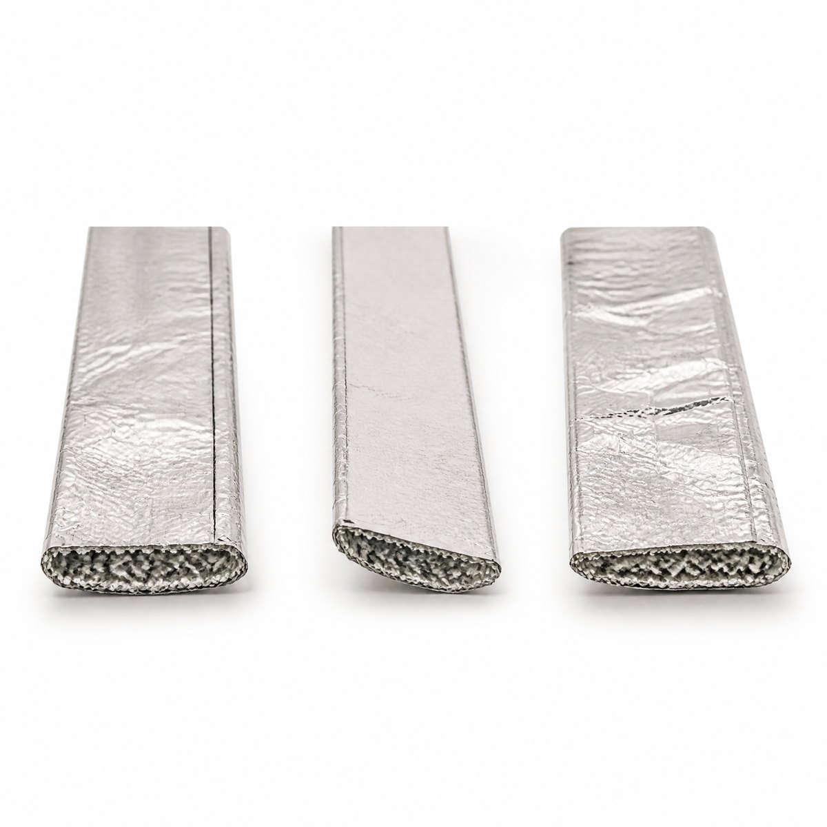
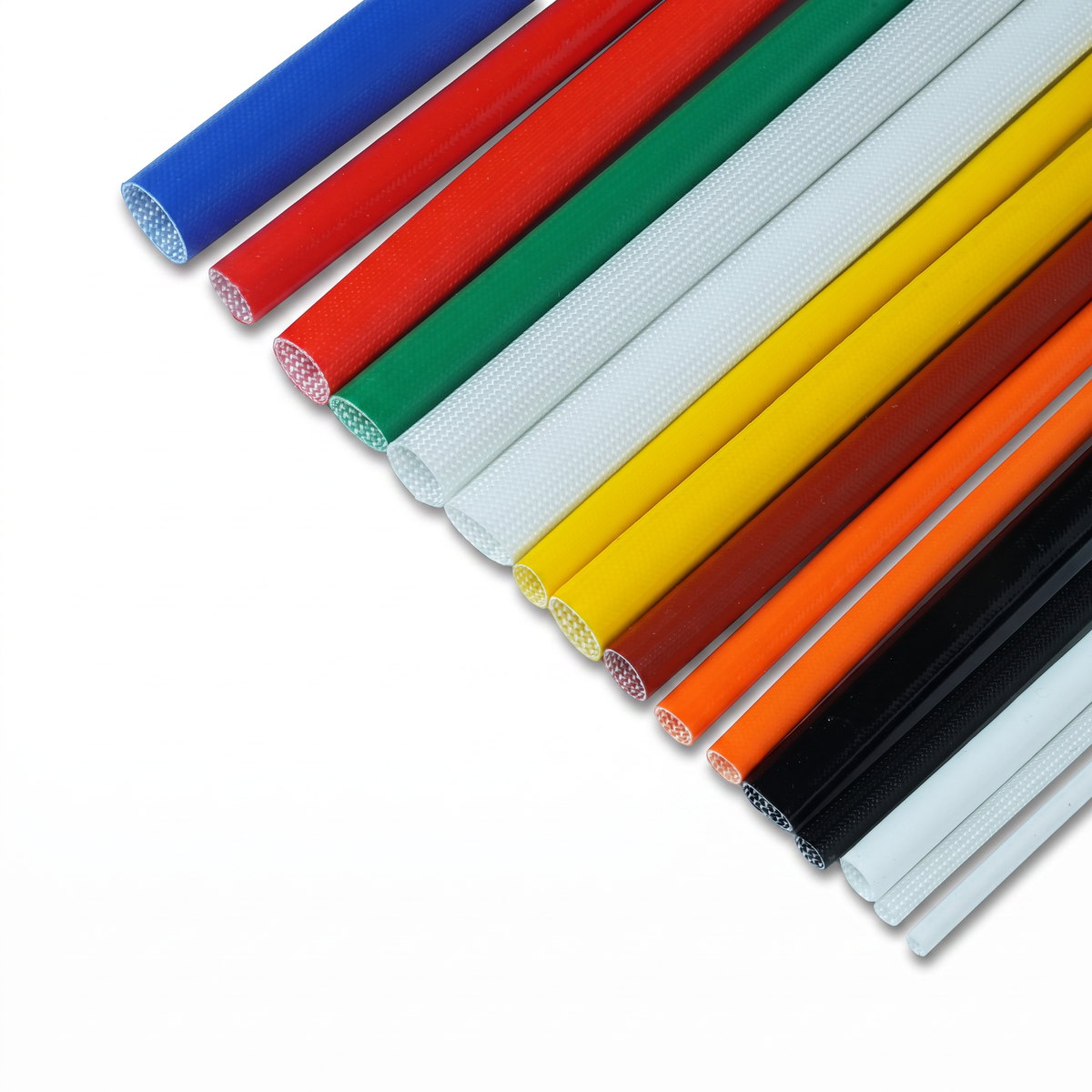
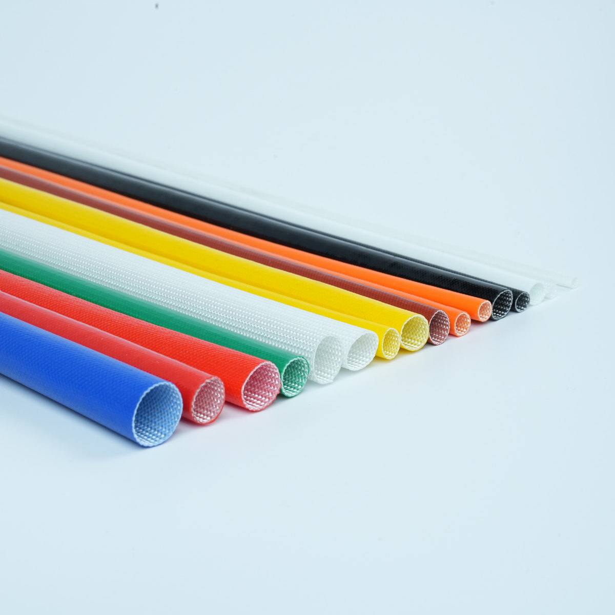
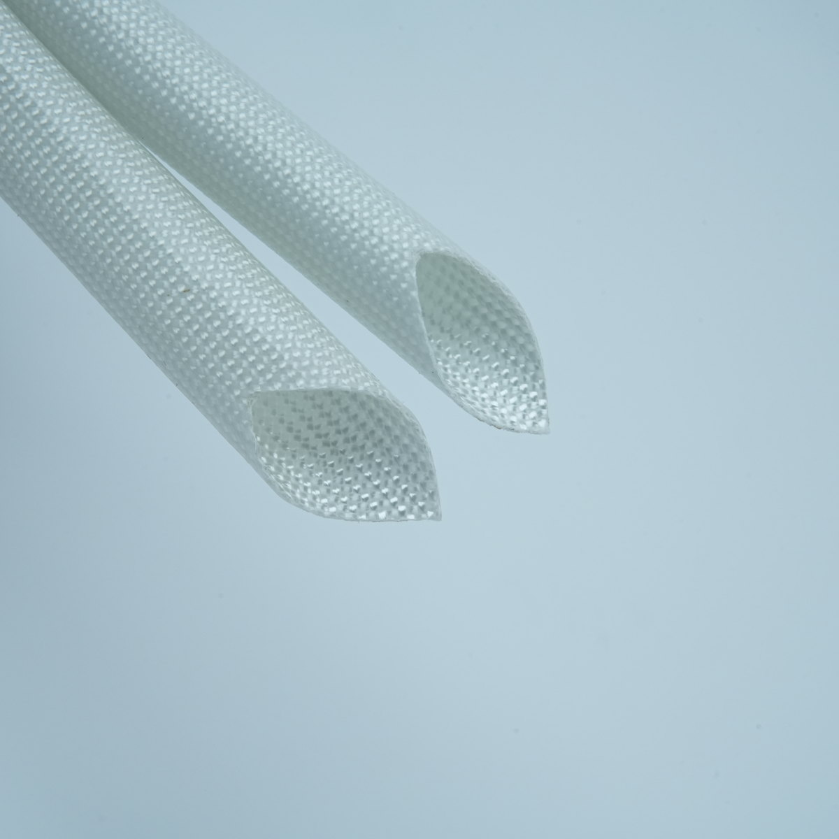
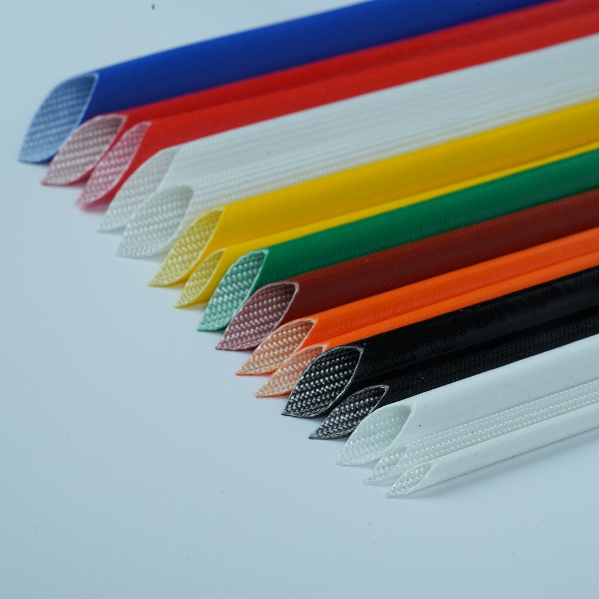
Routing an abrasion-resistant wire harness sleeve around bends and connectors is a critical skill in electrical assembly, automotive manufacturing, and industrial equipment design. When cables and wires experience constant flexing, vibration, or contact with sharp edges, the integrity of your entire system is at risk. A properly routed wire harness sleeve serves as the first line of defense, protecting conductors from abrasion, heat, and environmental damage while maintaining signal integrity and operational reliability.
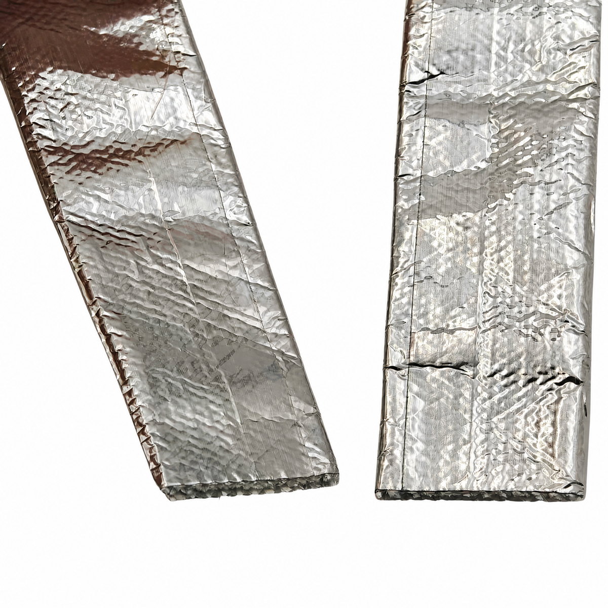
Proper wire harness routing improves protection and equipment lifespan. In automotive, aerospace, and industrial applications, cable paths around corners and connectors affect protection performance. This guide covers essential routing and installation practices for wire harness sleeves.
Understanding Wire Harness Sleeve Material Properties and Bend Requirements
Braided polyester, PPS, and high-temperature fiberglass sleeves have different bend limits and performance characteristics. Check the specified minimum bend radius before installation. Exceeding it may damage fibers, reduce protection, and eventually expose wire insulation.
Bend Radius Specifications and Material Selection
Bend radius defines how tightly a sleeve can curve without structural damage. Standard braided sleeves typically require 10–15 times the protected bundle diameter. A 0.5-inch bundle therefore needs approximately 5–7.5 inches of bend radius. Check the material specification before routing.
Material composition directly influences bend behavior and cable protection longevity. PPS sleeves provide superior temperature resistance and chemical compatibility compared to standard polyester but may require slightly larger bend radii in extremely tight configurations. High-temperature fiberglass sleeves excel in underhood automotive and industrial applications but demand careful handling during routing to prevent fiber separation. Selecting the correct material for your application's thermal, chemical, and mechanical environment is the foundational step before routing begins.
Connector Compatibility and Interference Management
Sleeve material can obstruct connector mating, terminal insertion, or waterproofing. OEM specifications commonly require a 0.25–0.5-inch clearance from the connector body. Check connector dimensions, mating direction, and strain relief requirements to avoid assembly interference.
Plan sleeve termination before assembly begins. Too little clearance can obstruct connector mating or crush wires; too much leaves wires exposed to abrasion. Measure the connector and set a suitable termination distance that balances coverage, access, and assembly requirements for each connector.
Routing Techniques for Bends, Tight Corners, and Complex Geometries
Successful routing of abrasion-resistant wire harness sleeve requires systematic planning, proper tool selection, and understanding how cable protection responds to bending forces. Whether navigating a 90-degree corner in an engine compartment or winding through a compact electronic enclosure, the techniques you employ determine whether your harness protection maintains contact with all conductors or develops gaps that expose internal wires to damage.
Progressive Bending and Bend-Radius Compliance
Progressive bending guides the harness through a gradual curve, spreading stress and reducing deformation and fiber compression. Around a 90-degree turn, use a 3–6-inch arc rather than a 1-inch radius to protect sleeve shape and maintain conductor support during installation where possible.
To achieve progressive bending, use flexible conduit supports, cable clamps, or routing guides that allow the wire harness sleeve to transition smoothly through its path. Avoid securing the sleeve tightly at the bend point itself; instead, place support points before and after the bend to define the overall curve shape without pinching. This technique is especially valuable when routing through engine compartments, industrial junction boxes, or aerospace panel cavities where space is limited and multiple bends occur within short distances.
Supporting Transitions Around Tight Connectors
At connector termination points, proper support prevents the wire harness sleeve from collapsing, twisting, or pulling away from the cable bundle during assembly or vibration cycles. Support the transition zone with a cable clamp positioned 0.5–1 inch before the connector, ensuring that harness protection remains evenly distributed even as external forces act on the connector body. For automotive and aerospace applications, support clamps rated for the operating temperature range and vibration environment are essential to prevent wire harness sleeve migration or separation.
The connector end of the cable protection typically requires special handling to prevent fraying or unraveling of braided material. Some installers apply a small amount of adhesive-lined shrink tubing at the sleeve terminus, creating a permanent bond that locks the braided structure in place. Others fold the sleeve back on itself slightly and secure it with a cable tie 0.25 inches behind the connector interface, allowing the exposed wire segment to transition into the connector while the sleeve end remains stable and visible for quality verification.
Installation Methods, Tools, and Quality Verification for Cable Protection
Proper installation of wire harness sleeve requires the right tools, systematic assembly sequences, and verification steps that confirm the cable protection is functioning as designed. Whether you are working with braided sleeves, woven designs, or split sleeves for retrofit applications, following proven installation protocols ensures consistent quality and long-term reliability.
Pre-Installation Planning and Bundle Configuration
Arrange conductors without crossings or twists that create gaps. Measure the bundle at several points and size the sleeve for its maximum cross-section. Choose an inner diameter 10–20 percent larger than that measurement to ease installation while maintaining adequate contact and abrasion protection as specified.
Mark the intended routing path with temporary tape or markers before installing harness protection. Identify all bend points, connector locations, and support positions so installation proceeds without confusion. For complex harnesses with multiple branches or high-density wiring, creating a routing diagram ensures that cable protection does not interfere with adjacent equipment or create installation conflicts during final assembly.
Threading, Securing, and Bend-Point Management
Threading wire harness sleeve over an assembled bundle requires patience and correct technique to prevent snagging or uneven coverage. Begin at one end of the bundle and gradually feed the sleeve onto the conductors, ensuring that the material remains centered and untwisted throughout its length. For long harnesses, support the sleeve at multiple points during threading to prevent sagging or bunching at specific locations. Once the sleeve is positioned, secure it at key intervals using adhesive-lined shrink tubing, cable ties, or clamps.
At planned bend points, apply gentle pressure by hand to gradually guide the cable protection into the intended curve shape. Simultaneously secure supporting clamps or guides that lock the sleeve into the final routing path. Allow the harness protection to settle naturally around the bundle rather than forcing abrupt shape changes. This gradual approach maintains the sleeve's structural integrity and ensures that cable protection remains effective throughout the entire bending radius.
Quality Checks and Verification of Harness Protection Effectiveness
After installation, conduct visual and tactile inspections to confirm that wire harness sleeve provides complete coverage and remains properly positioned around all conductors. Gently flex the harness at bend points while observing that the sleeve moves smoothly with the bundle and does not pinch, gap, or twist. Check that no bare wire is visible where the sleeve terminates or at any intermediate support point. Measure the remaining clearance between the sleeve end and connector body to verify compliance with your assembly specification. For critical applications, document photographic evidence of installed harness protection from multiple angles, creating a quality record for traceability and future reference.
FAQ
What is the recommended minimum bend radius for standard braided wire harness sleeve?
The recommended minimum bend radius for standard braided wire harness sleeve is typically 10–15 times the diameter of the bundle being protected. For example, a 0.5-inch bundle should have a bend radius of at least 5–7.5 inches. Exceeding this bend radius limit damages internal fibers, reduces cable protection effectiveness, and can lead to conductor exposure over time. Always verify the specific bend radius requirement for your sleeve material and consult the manufacturer's technical documentation before routing harness protection through tight geometries.
How far back should wire harness sleeve be pulled from a connector?
Wire harness sleeve should be pulled back 0.25–0.5 inches from the connector body to prevent material bunching, interference with terminal insertion, and improper connector seating. This distance ensures that your cable protection does not obstruct the connector interface while maintaining adequate coverage of exposed conductors between the sleeve terminus and connector pin area. Different connector styles and OEM specifications may require slightly different termination distances, so always confirm the exact requirement for your specific application and connector type.
Can split wire harness sleeve be used for retrofit applications around existing connectors?
Yes, split wire harness sleeve is an excellent choice for retrofit applications where existing connectors and wire configurations cannot be modified. Split sleeves open lengthwise, allowing harness protection to be wrapped around assembled bundles without requiring disassembly or rework. Installation involves opening the split sleeve, wrapping it around the bundle, and securing the seam with adhesive-lined shrink tubing or cable ties. While split sleeves offer convenience for retrofit scenarios, continuous braided sleeves remain superior for new installations because continuous designs provide better compression contact and more uniform cable protection across the entire bundle.
 EN