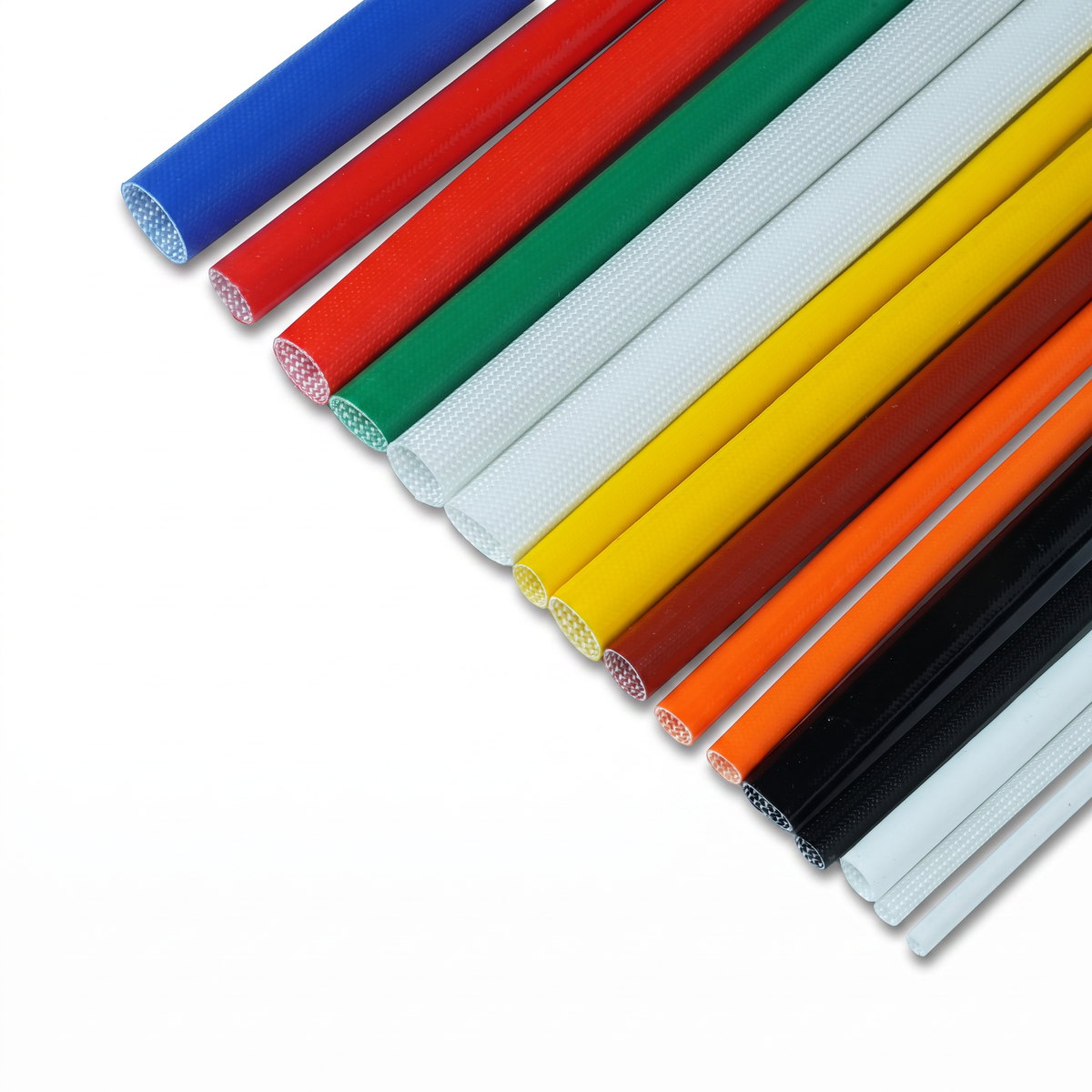
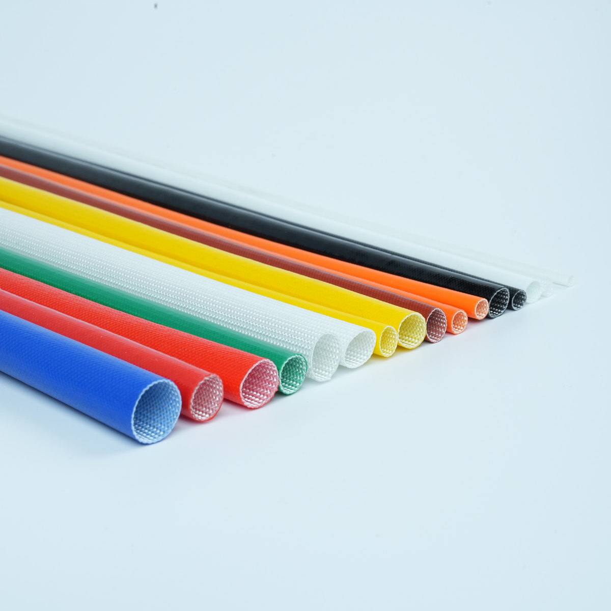
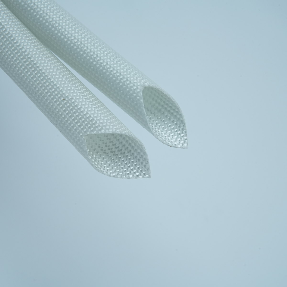
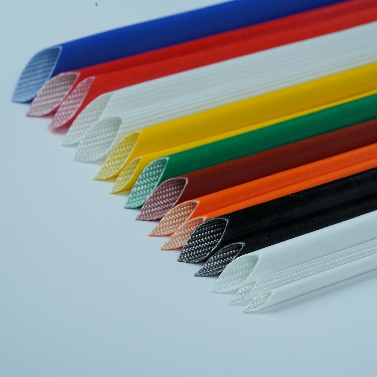
Defining fit and tolerance requirements for fiberglass sleeving is essential for ensuring reliable performance in demanding industrial and electrical applications. Fiberglass sleeving serves as a critical component in high temperature insulation systems, protecting wires and cables from thermal degradation, mechanical abrasion, and environmental exposure. However, selecting the correct dimensions and tolerances requires a systematic understanding of application requirements, material properties, and performance standards. This guide walks you through the process of establishing precise fit and tolerance specifications that optimize both protection and installation efficiency.
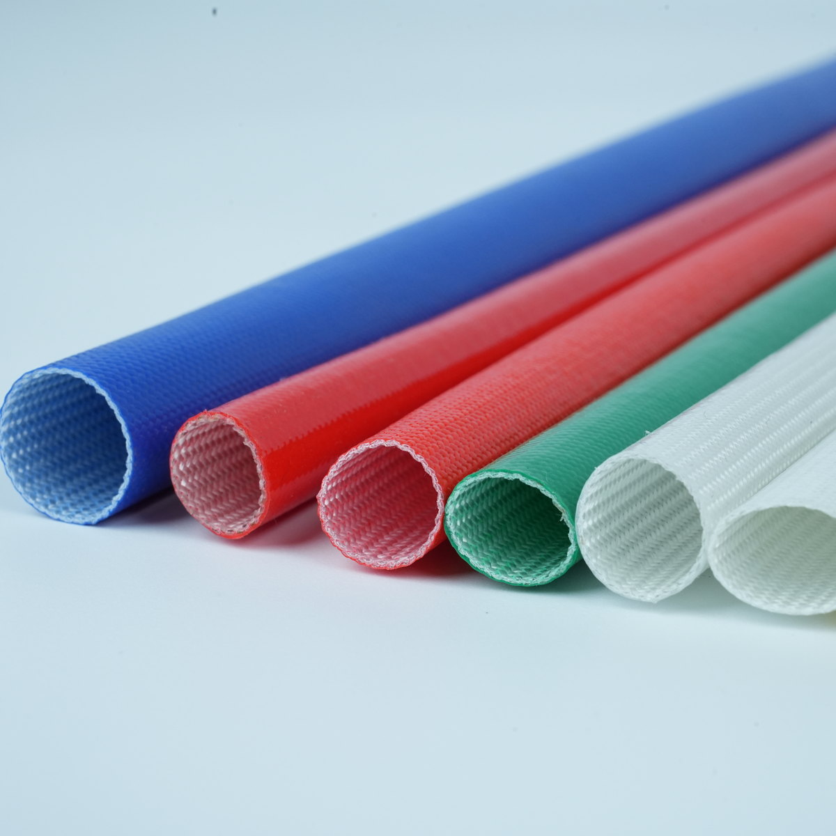
The process of defining fit and tolerance for fiberglass sleeving involves evaluating multiple factors, including wire diameter, operating temperature range, mechanical stress conditions, and regulatory compliance requirements. Tolerance specifications directly impact the effectiveness of wire protection, the ease of installation, and the long-term durability of the insulation system. Understanding industry standards and application-specific demands allows engineers and procurement professionals to make informed decisions that reduce installation errors, minimize material waste, and ensure consistent product quality across manufacturing and assembly operations.
Understanding Fiberglass Sleeving Dimensions and Fit Categories
Inner Diameter Specifications and Wire Compatibility
The inner diameter of fiberglass sleeving must accommodate the conductor or cable bundle it protects while maintaining sufficient contact to prevent shifting during thermal cycling. High temperature insulation products like fiberglass sleeving are typically manufactured in standard sizes ranging from 1/8 inch to several inches in diameter, with custom sizes available for specialized applications. Determining the correct inner diameter requires measuring the wire or cable bundle diameter and applying a fit classification that balances snug contact with installation practicality. An oversized bore allows sleeving to slip during operation, compromising wire protection and potentially exposing conductors to damage. Conversely, an undersized bore creates installation difficulties and may crush delicate wire insulation during assembly.
Outer Diameter Tolerance and Mechanical Clearance
The outer diameter of fiberglass sleeving affects how the component integrates with surrounding equipment, connectors, and conduit systems. Tolerance control on the outer diameter becomes critical when fiberglass sleeving must pass through fixed openings, terminate within terminal blocks, or nest against adjacent components. Manufacturers typically apply tolerance bands that account for variations in the braiding or wrapping process while ensuring that the finished product remains within acceptable limits for assembly environments. Electrical insulation applications often require tighter outer diameter tolerances to accommodate standard connector bodies and terminal housings without modification or rework.
Establishing Tolerance Specifications Based on Application Requirements
Thermal Cycling and Dimensional Stability
High temperature insulation systems experience repeated thermal cycles that can cause fiberglass sleeving to expand and contract. Tolerance specifications must account for this thermal behavior by establishing baseline dimensions at room temperature and then calculating allowable shrinkage or expansion at both minimum and maximum operating temperatures. Fiberglass materials with phenolic resin binders typically exhibit lower thermal growth compared to silicone-based systems, allowing tighter tolerances in extreme temperature applications. Engineers defining tolerance bands must consider not only the sleeving itself but also the thermal expansion of the protected wire or cable, ensuring that fit classifications remain valid across the entire operating temperature range.
Mechanical Stress and Vibration Resistance
Wire protection in high-vibration industrial environments demands tolerance specifications that prevent sleeving from sliding along the conductor during mechanical stress. Machines with rotating shafts, reciprocating actuators, and impact loads create dynamic conditions that test the grip between fiberglass sleeving and the protected wire. Tighter inner diameter tolerances provide better retention but increase installation labor and potential for conductor damage. Conversely, looser tolerances facilitate faster assembly but risk inadequate wire protection under operating stress. Balancing these competing demands requires testing the proposed tolerance in actual or simulated service conditions before finalizing specifications for high-volume production.
Installation Accessibility and Labor Efficiency
Practical installation considerations heavily influence tolerance decisions in manufacturing and assembly environments. Technicians assembling electrical systems must be able to slide fiberglass sleeving onto wires and cables without excessive force or specialized tools. Tolerance specifications that are too tight create bottlenecks in production, increase installation errors, and may cause damage to conductors or insulation. Collaboration between engineering and assembly teams ensures that tolerances balance protective performance with realistic installation constraints. Many industries adopt standard tolerance grades that recognize the inherent trade-off between fit tightness and installation speed, allowing purchasing departments to communicate requirements clearly to suppliers and manufacturers.
Implementing Standards and Quality Verification Processes
Industry Standards and Regulatory Compliance
Wire protection standards such as UL, IEC, and MIL specifications define performance requirements for high temperature insulation and electrical insulation materials. These standards often reference tolerance grades and fit classifications that guide manufacturers and end-users in establishing compatible specifications. Fiberglass sleeving used in aerospace, automotive, and industrial electrical applications typically must comply with specific dimensional standards documented in engineering drawings and material specifications. Referencing applicable standards in procurement documents ensures that suppliers manufacture components that meet recognized performance criteria and provides a common language for defining acceptance criteria during incoming inspection.
Measurement Methods and Acceptance Criteria
Verifying that fiberglass sleeving meets defined tolerance specifications requires appropriate measurement tools and trained personnel. Inner diameter measurement typically uses go/no-go gauges, micrometers, or precision calipers applied at multiple points along the sleeving length. Outer diameter verification employs similar techniques, with additional consideration for the braided or wrapped fiber geometry that may create slight measurement variations depending on gauge position. Quality assurance procedures should specify measurement locations, acceptable variation ranges, and documentation requirements to ensure consistent acceptance decisions. Documented measurement records provide traceability for high-reliability applications and support continuous improvement efforts by identifying systematic variation patterns that suggest process adjustments.
FAQ
What tolerance range is standard for fiberglass sleeving inner diameter?
Standard tolerance ranges for fiberglass sleeving inner diameter typically fall between plus or minus 0.03 to 0.06 inches, depending on the base diameter and application requirements. Smaller diameter sleeving generally receives tighter tolerances, while larger diameters may accept slightly wider tolerance bands. High temperature insulation applications often employ tighter tolerances to ensure consistent wire protection and reduce slip risk during thermal cycling. Specific tolerance requirements should be confirmed with the manufacturer based on the exact nominal size and intended application environment to ensure compliance with your engineering specifications.
How do high temperature conditions affect fiberglass sleeving fit and tolerance?
High temperature insulation environments cause fiberglass sleeving to experience thermal expansion and contraction cycles that alter the effective fit between sleeving and conductor. Most fiberglass materials expand at rates ranging from 15 to 25 parts per million per degree Celsius, depending on the resin system and fiber orientation. Tolerance specifications must account for maximum and minimum dimensional changes across the full operating temperature range to maintain adequate wire protection and prevent excessive looseness. Testing fiberglass sleeving samples at both room temperature and maximum service temperature helps validate that your tolerance specification remains functional under all conditions and prevents unexpected fit problems during field deployment.
How can tolerance specifications balance protection performance with installation speed?
Achieving optimal balance between electrical insulation effectiveness and installation efficiency requires collaboration between product design, engineering, and manufacturing teams. Tolerance specifications that are too tight create installation delays and damage risk, while overly loose specifications compromise wire protection during mechanical stress or thermal cycling. Industry-standard fit classifications such as close, normal, and free fits provide recognized frameworks for this trade-off, allowing teams to select categories that match their specific priorities. Pilot production runs using proposed tolerance specifications help identify practical installation challenges before full-volume manufacturing begins, ensuring that final specifications deliver realistic performance across protection, assembly speed, and quality metrics.
 EN