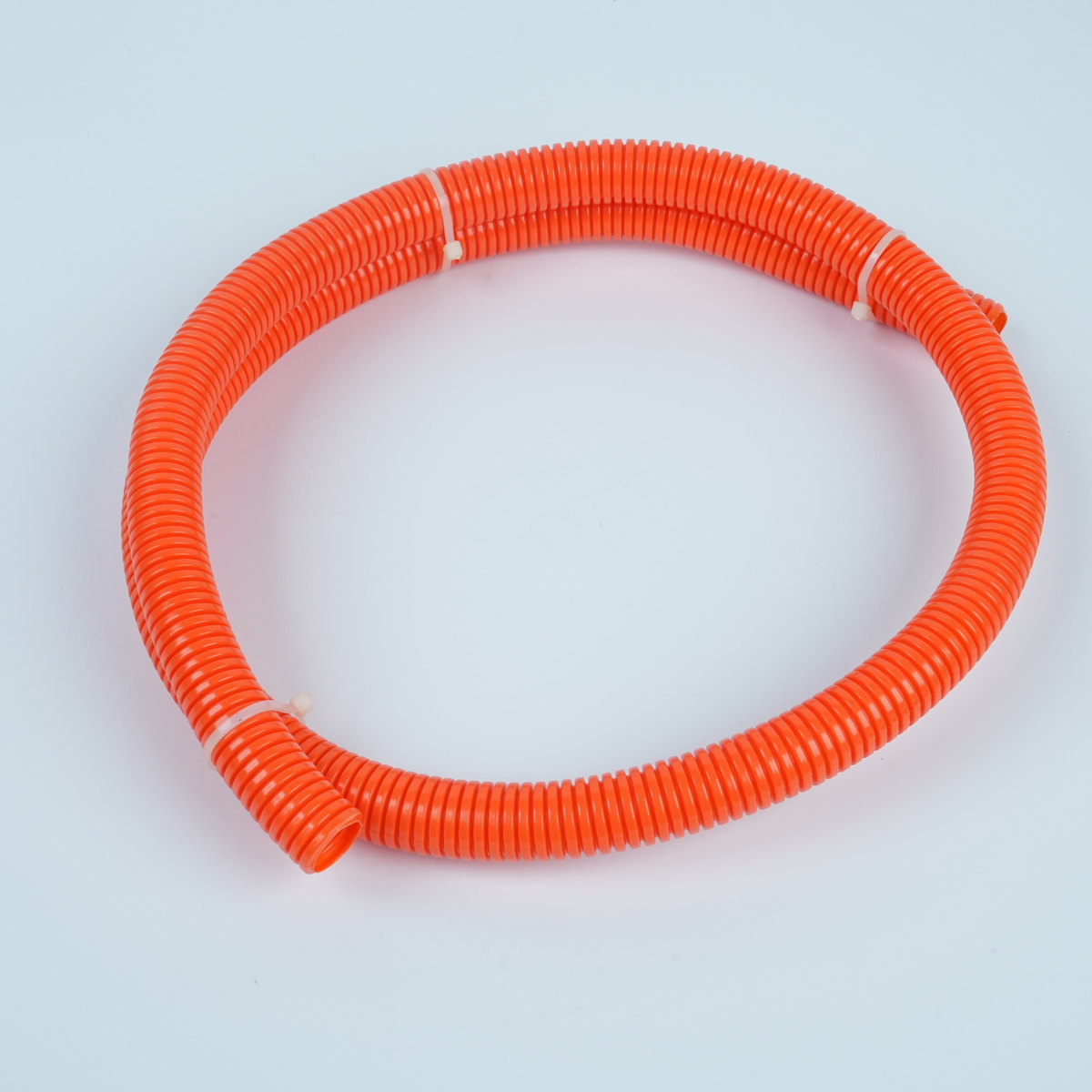
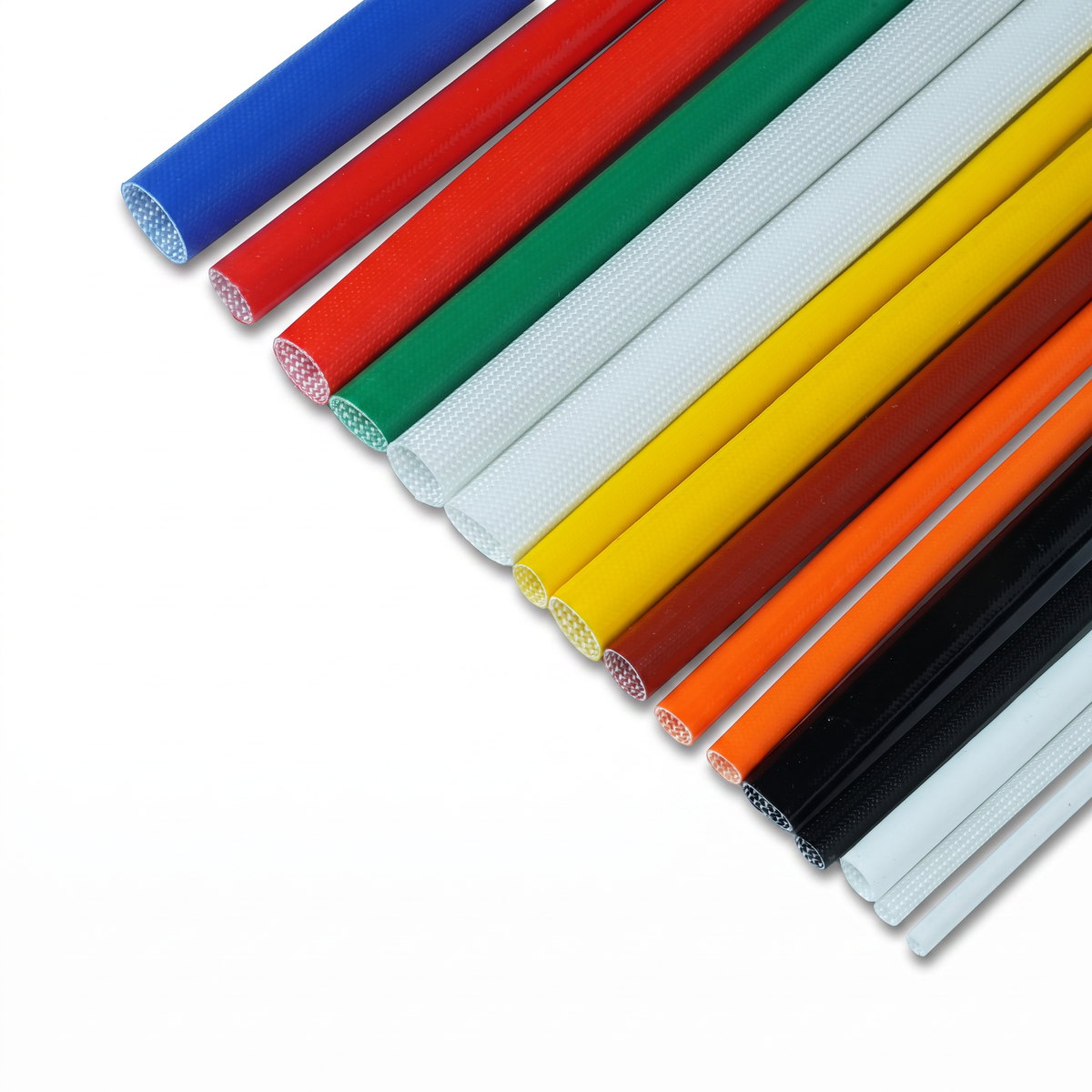
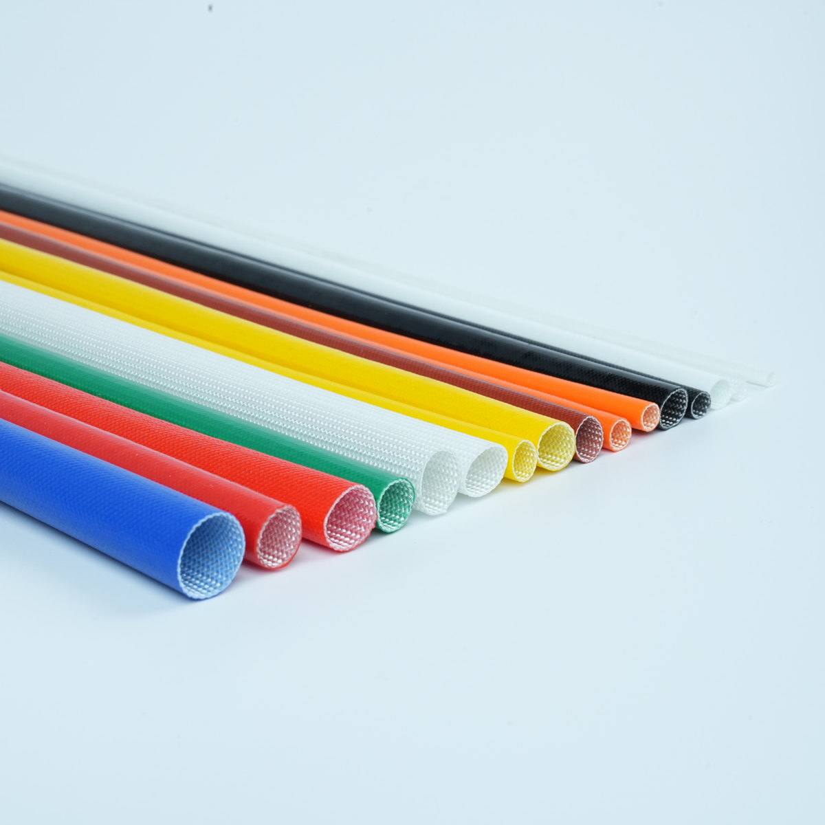
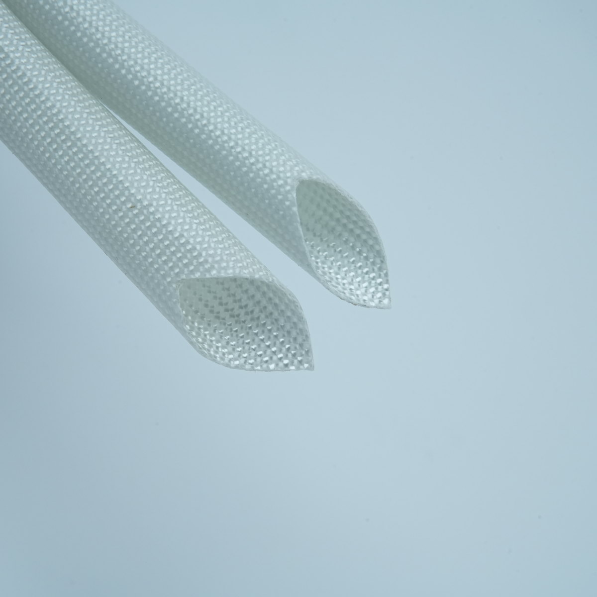
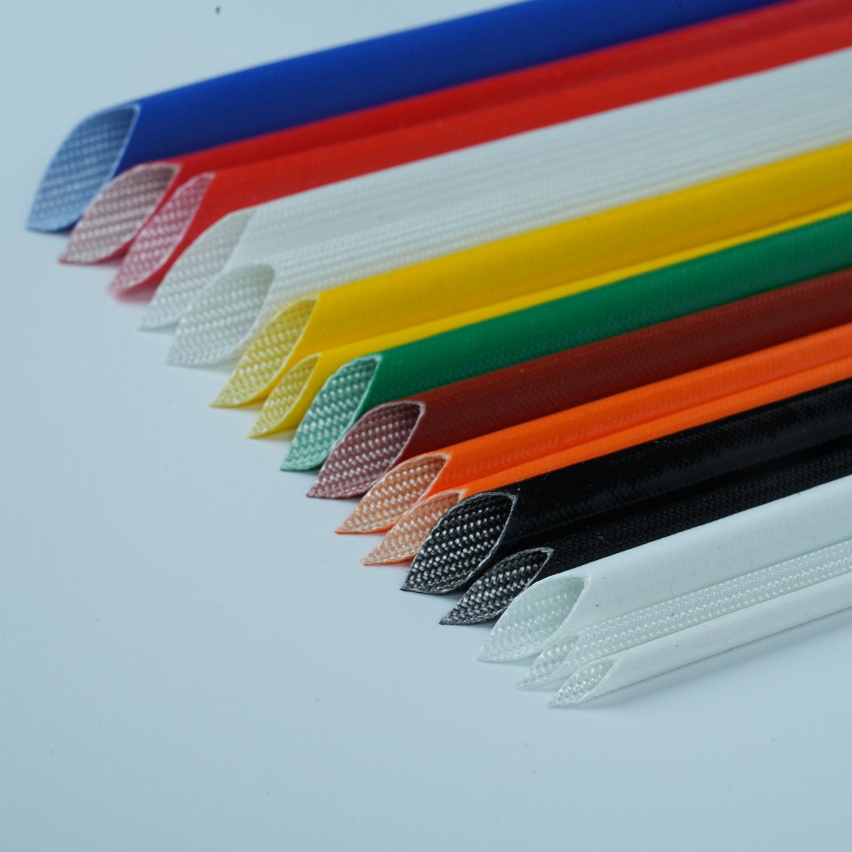
Defining fit and tolerance requirements for corrugated conduit is essential for ensuring reliable wire protection and operational performance in industrial and automotive applications. Tolerance specifications directly impact how well the conduit protects wires, accommodates thermal expansion, and maintains dimensional stability across product lifecycles. Engineers and procurement teams must establish clear, measurable criteria that align with application demands, environmental conditions, and assembly requirements.
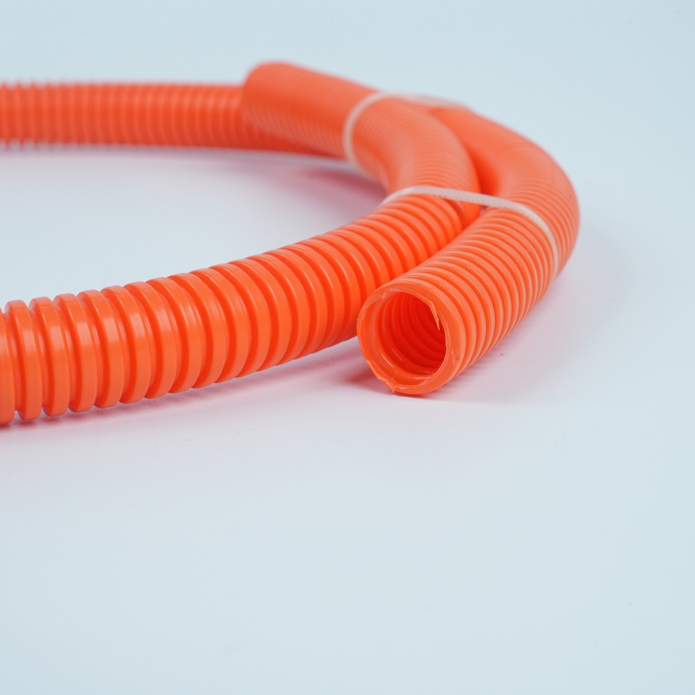
Understanding the relationship between fit tolerances and wire protection performance is critical for selecting the right flexible conduit solution. Proper tolerance definition prevents common issues such as excessive slippage, compression damage to internal wires, and premature failure under vibration or thermal cycling. This guide walks through the key parameters, measurement methods, and decision frameworks needed to establish accurate fit and tolerance specifications for your corrugated conduit applications.
Understanding Fit and Tolerance Fundamentals
What Fit and Tolerance Mean for Flexible Conduit
Fit refers to the relationship between the inner diameter of the corrugated conduit and the outer diameter of the wire bundle or cable it protects. Tolerance defines the acceptable range of variation in these dimensions. In flexible conduit applications, fit tolerance directly affects how snugly the conduit grips the wire bundle, whether slippage occurs during installation or operation, and how much radial stress is applied to the wires inside. Tighter tolerances improve wire protection but can complicate assembly, while looser tolerances simplify installation but may reduce protective effectiveness.
Why Tolerance Specification Matters in Wire Protection
Improper fit tolerances are a leading cause of wire protection failures in industrial and automotive harness applications. If the corrugated conduit is too loose, wires may shift inside the conduit during vibration, leading to abrasion and eventual insulation failure. Conversely, if the conduit is too tight, installation forces can damage delicate wire insulation or create stress points that fail under thermal cycling. By defining precise fit and tolerance requirements upfront, engineers minimize assembly errors, reduce warranty claims, and ensure consistent performance across production batches and throughout the product's service life.
Key Parameters for Defining Corrugated Conduit Tolerances
Inner Diameter and Wall Thickness Specifications
The inner diameter (ID) of the corrugated conduit is the primary dimension that determines fit with the wire bundle. When specifying the corrugated conduit, engineers must define the nominal ID, the upper tolerance limit (maximum ID), and the lower tolerance limit (minimum ID). Wall thickness also influences the effective ID and overall structural integrity. For wire protection applications, tighter ID tolerances reduce variation in the final assembled product and help ensure consistent cable strain relief. A typical tolerance range for flexible conduit might span 0.10 to 0.20 inches, depending on the nominal size and material properties of the nylon or polyester base material.
Spiral Pitch and Dimensional Consistency
The spiral pitch of corrugated conduit affects both its flexibility and its dimensional stability. Uniform spiral pitch ensures that the corrugated conduit maintains consistent ID along its length, which is critical for automotive harness applications where wires must fit snugly and uniformly. Variation in spiral pitch can create tight spots that damage wires during installation or loose sections where wires shift. Specifying pitch tolerance typically involves defining a maximum allowable variation per unit length and establishing sampling inspection protocols to verify consistency during production runs.
Establishing Fit Tolerance Requirements for Your Application
Assessing Wire Bundle Diameter and Configuration
The first step in defining corrugated conduit fit tolerance is accurately measuring and documenting the outer diameter (OD) of the wire bundle that will be protected. For single-wire applications, the OD is straightforward; for complex harnesses with multiple bundled wires, the effective OD depends on how tightly the wires are bound and how they compress under external pressure. Engineers must measure at multiple cross-sections along the harness to identify the maximum OD that the corrugated conduit must accommodate. This maximum wire OD then becomes the baseline for determining the minimum acceptable ID of the corrugated conduit, with additional tolerance margin added to prevent jamming and excessive installation force.
Setting Clearance and Compression Margins
Once the wire bundle diameter is known, engineers must decide on appropriate clearance margins. A typical approach is to define a minimum clearance of 0.03 to 0.10 inches between the outer wire surface and the inner surface of the corrugated conduit, depending on application severity and material compatibility. Smaller clearances provide tighter grip and better vibration damping but require stricter manufacturing control. Larger clearances simplify assembly but may allow wire movement. For automotive harness applications requiring high vibration resistance, engineers often specify the conduit to compress the wire bundle by 10 to 20 percent, creating a press-fit that resists shifting while remaining within material stress limits and not damaging the wire insulation.
Practical Implementation and Measurement Methods
Standard Measurement Procedures for Quality Control
Effective tolerance management requires establishing repeatable measurement protocols. The corrugated conduit inner diameter should be measured at multiple points along the sample length—typically at least three locations—to capture any variation in spiral pitch or extrusion consistency. Measurement tools include precision calipers, go/no-go gauges, or automated vision systems for high-volume production. For wire bundle diameter, measurement should occur at the point where the bundle will be inserted into the corrugated conduit, with consistent measurement technique to eliminate error. Documented inspection records create a quality baseline and help identify production trends that might require corrective action.
Tolerance Stack-Up and Assembly Variability
In real-world assembly, multiple tolerance sources combine to affect final fit performance. Variability in corrugated conduit ID, wire bundle diameter, conduit cut length, and wire positioning all contribute to tolerance stack-up. Engineers must account for cumulative variation when setting individual component tolerances. If the corrugated conduit tolerance and wire bundle tolerance ranges both sit at the extremes simultaneously, the assembled fit might become unacceptable. Statistical tolerance analysis or Monte Carlo simulation can help predict the probability distribution of final fits and guide tolerance allocation decisions. This analysis ensures that corrugated conduit specifications remain achievable in manufacturing while meeting assembly and performance requirements.
Testing Fit Performance Under Operating Conditions
Once fit and tolerance specifications for the corrugated conduit are defined, validation testing confirms that the design functions as intended. Vibration testing simulates on-road or in-service mechanical stress to verify that wires remain securely positioned within the conduit without excessive movement. Thermal cycling tests subject the assembled harness to temperature extremes to check whether differential material expansion creates slippage or unintended compression. Tensile pull tests verify that the wire bundle does not slip through the corrugated conduit under pulling force. These performance tests provide empirical evidence that tolerance specifications deliver adequate wire protection and justify specification decisions to design and manufacturing teams.
FAQ
What happens if corrugated conduit tolerance is too loose?
If the corrugated conduit tolerance allows the inner diameter to be significantly larger than the wire bundle, wires may shift and slide inside the conduit during vibration or thermal cycling. This movement causes abrasion of the wire insulation, potentially leading to short circuits, electrical failure, or safety hazards. Loose tolerance also reduces the protective benefit of the conduit against external impacts and contaminants. To avoid these issues, specify a fit tolerance that keeps the wire bundle snug within the corrugated conduit throughout its service life.
How tight should the fit be between the wire and flexible conduit?
The ideal fit for flexible conduit depends on application severity and material properties. For moderate-duty applications, a clearance of 0.05 to 0.08 inches between wire and corrugated conduit works well, offering good vibration damping with manageable assembly force. For high-vibration automotive harness applications, tighter fits with 10 to 20 percent compression of the wire bundle provide superior protection. Always test the specified fit in your assembly process to ensure that installation forces remain within tool capability and wire insulation is not damaged during insertion into the corrugated conduit.
What measurement tools are best for verifying corrugated conduit tolerances?
For small-scale verification, precision digital calipers deliver adequate accuracy for measuring the inner diameter of corrugated conduit. For production environments, go/no-go gauges streamline inspection and reduce measurement variability. High-volume manufacturers often employ automated vision systems or laser measurement instruments to inspect the corrugated conduit ID at multiple locations per sample, ensuring consistency and providing statistical data for process control. Whichever tool you choose, establish a documented calibration schedule and train operators consistently to maintain measurement reliability.
 EN