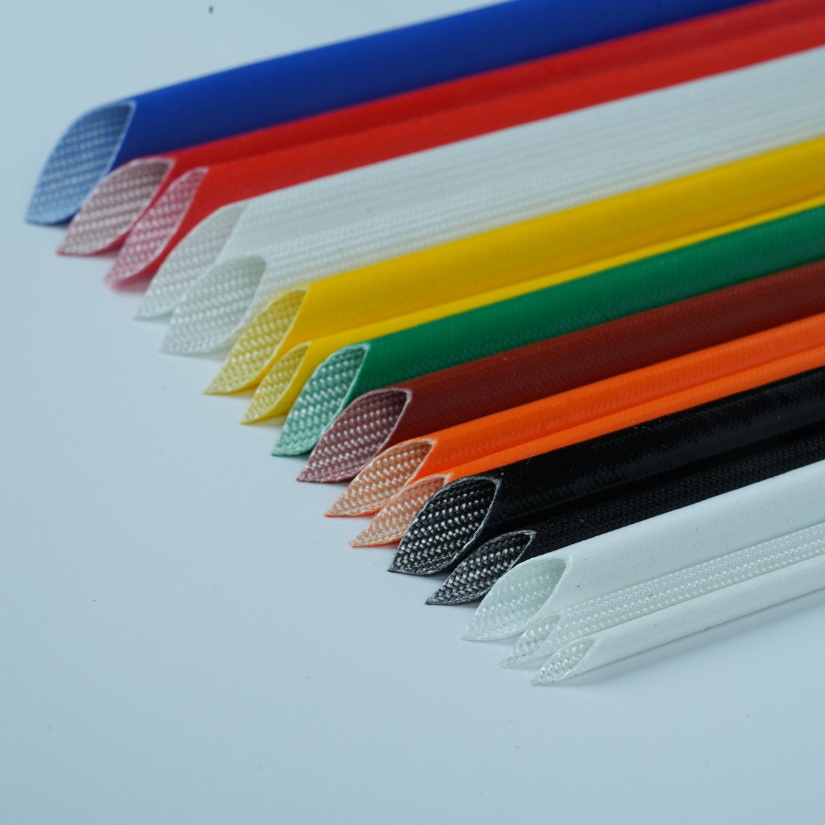
Selecting the right materials for compact electronic assemblies requires careful attention to thermal stability, chemical resistance, and dielectric performance. PTFE sleeving has become an industry standard for applications demanding exceptional reliability under demanding conditions. Whether you are designing aerospace wiring harnesses, automotive power modules, or medical device connectors, understanding how to specify PTFE sleeving correctly ensures your assembly meets both functional requirements and regulatory standards.
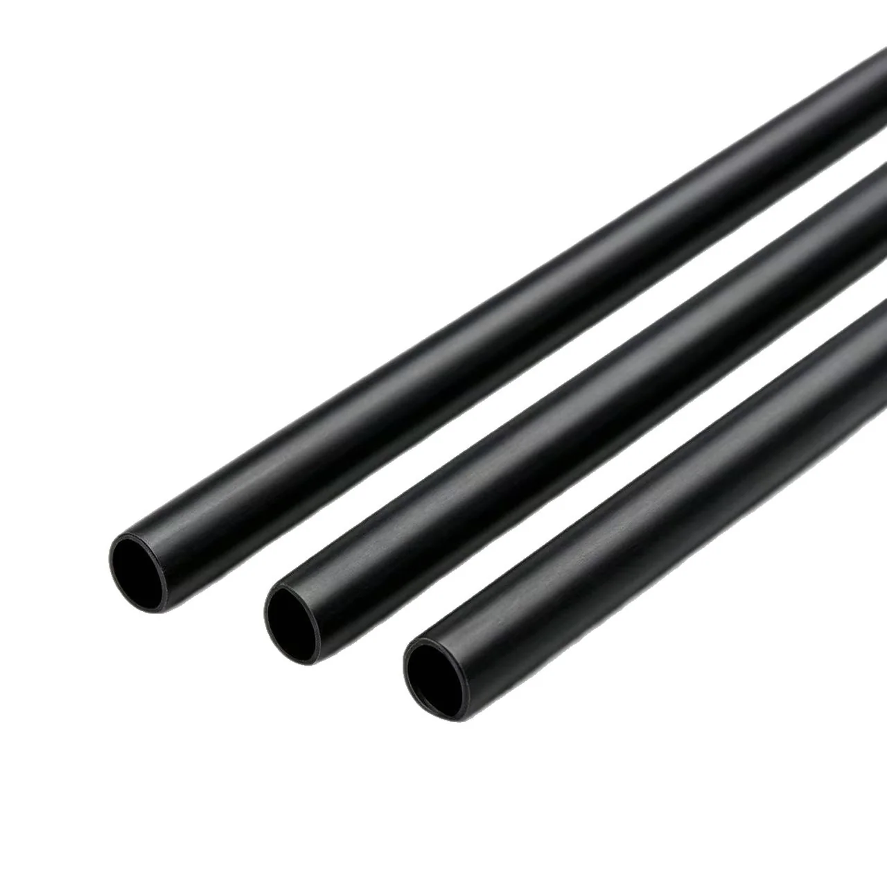
The specification process extends beyond simply choosing a tubing diameter. Effective cable protection and electrical insulation demand that you evaluate wall thickness, shrink ratios, operating temperature ranges, and compatibility with your assembly substrates. This guide walks you through the practical decision points that determine whether PTFE sleeving will deliver the durability and performance your compact electronic assemblies require.
Understanding PTFE Sleeving Material Properties
Core Characteristics of High Temperature Performance
PTFE, commonly known by its Teflon brand, exhibits thermal stability unmatched by most polymeric alternatives. When you specify PTFE sleeving for high temperature applications, you gain material that maintains flexibility and dielectric strength even at 200°C continuous exposure and brief excursions to 260°C. This exceptional thermal window allows compact electronic assemblies to operate without thermal degradation of insulation or embrittlement of the protective layer. The material resists oxidation at elevated temperatures, ensuring long-term reliability in confined spaces where heat dissipation challenges limit your design options.
Chemical Resistance and Operational Environment
Beyond thermal capability, PTFE sleeving delivers outstanding chemical resistance that protects against oils, solvents, and corrosive fluids common in industrial settings. For cable protection in harsh environments, this resistance prevents degradation pathways that would compromise the electrical insulation layer beneath. The nonpolar nature of PTFE makes it inherently resistant to most organic and inorganic substances, enabling your compact electronic assemblies to function reliably in chemical manufacturing plants, automotive engine compartments, and marine environments where other sleeving materials would fail.
Selecting Appropriate Dimensions and Wall Thickness
Matching Sleeving Diameter to Your Wire and Connector Geometry
Specifying the correct PTFE sleeving diameter represents your first critical decision point. The inner diameter must accommodate your wire bundle while allowing adequate space for thermal expansion without excessive looseness that compromises mechanical protection. In compact electronic assemblies, space constraints often force you to choose between multiple smaller gauge wires bundled together versus fewer larger conductors. When selecting PTFE sleeving, evaluate your actual wire outer diameter plus any existing insulation, then specify a sleeving size that shrinks to approximately 90 percent of the final bundle diameter for optimal contact and cable protection without mechanical stress.
Wall Thickness Requirements for Durability
PTFE sleeving wall thickness directly influences abrasion resistance, puncture resistance, and long-term durability in your assembly. Standard wall thicknesses range from 0.015 inches to 0.125 inches depending on application severity. For high temperature environments, thicker walls provide thermal buffering and extended service life under flexing and mechanical stress. Compact electronic assemblies subjected to thermal cycling demand sufficient wall thickness to resist fatigue crack initiation, particularly at connection points where stress concentrations develop. Calculate wall thickness requirements by considering vibration exposure, thermal cycling frequency, and the severity of adjacent sharp edges or mechanical contact points that could accelerate wear.
Integration Strategies for Cable Protection and Electrical Insulation
Installation Methods and Assembly Compatibility
PTFE sleeving typically comes in two forms: standard tubing requiring mechanical assembly, and heat-shrinkable variants that tighten around the wire bundle when heated. Heat-shrinkable PTFE sleeving offers superior cable protection because the shrinking action pulls the material tightly against the underlying insulation, eliminating gaps where moisture or contaminants could accumulate. For compact electronic assemblies, heat-shrinkable options minimize installation time and reduce the risk of improper fit. Specify the appropriate shrink ratio for your application, typically 2:1, 3:1, or 4:1, ensuring your heat-shrink oven temperature remains below the degradation threshold while achieving consistent shrinkage across all assembly positions.
Thermal Management and Performance Verification
Once installed, PTFE sleeving must maintain electrical insulation integrity under thermal stress. The material expands and contracts with temperature cycling, creating mechanical forces at terminal connections and interfaces. When specifying PTFE sleeving for high temperature applications, verify that your assembly design accommodates this thermal movement without creating separation at connection points. Compact electronic assemblies benefit from PTFE's low thermal conductivity, which reduces heat transfer between adjacent circuits while protecting individual wires from thermal crossover. Conduct thermal testing at your specified operating temperature range, including thermal cycling simulations that replicate real-world duty cycles, to confirm that electrical insulation remains intact and cable protection performs as intended.
Regulatory Compliance and Performance Standards
Electrical and Safety Certifications
PTFE sleeving used in compact electronic assemblies must meet established electrical standards including UL 224 for flexible dielectric tubing and UL 1441 for heat-shrinkable materials. These standards establish electrical insulation values, temperature ratings, and flammability classifications that define acceptable performance. When you specify PTFE sleeving for regulated industries such as aerospace, automotive, or medical device manufacturing, verify that your selected material carries appropriate certifications from recognized testing laboratories. Documentation of compliance ensures regulatory approval and demonstrates that your cable protection strategy meets industry requirements. High temperature applications demand particular attention to temperature index ratings and continuous operating limits, which directly influence the acceptable service life of your compact electronic assemblies.
Quality Assurance and Material Validation
Specification of PTFE sleeving should include material testing protocols that verify electrical insulation thickness, dielectric strength, and thermal stability. Conduct incoming inspection testing that confirms wall thickness consistency, validates shrink ratios for heat-shrinkable variants, and verifies that the material exhibits the specified electrical and mechanical properties. Compact electronic assemblies serving critical applications benefit from material traceability and batch documentation that confirms consistent manufacturing quality. Establish acceptance criteria that require electrical insulation testing after installation, thermal cycling simulation, and accelerated aging protocols that simulate extended service life, ensuring your sleeving selection delivers reliable cable protection throughout your assembly lifetime.
FAQ
What temperature range should I specify for PTFE sleeving in a high temperature engine compartment application?
For automotive engine compartments, specify PTFE sleeving rated for continuous operation at 200°C with brief excursions to 260°C. This rating ensures electrical insulation and cable protection remain intact during normal engine operation and thermal transient events. Verify that your selected sleeving carries UL or comparable certification confirming these temperature limits.
How does PTFE sleeving compare to other materials for electrical insulation in compact spaces?
PTFE sleeving delivers superior high temperature performance compared to PVC, polyolefin, or silicone alternatives. While PTFE costs more, its exceptional chemical resistance, thermal stability, and dielectric properties make it the preferred choice when cable protection and electrical insulation must endure demanding conditions. Compact electronic assemblies benefit from PTFE's low outgassing characteristics and minimal thermal expansion, reducing stress on connections.
Should I use standard or heat-shrinkable PTFE sleeving for production assembly?
Heat-shrinkable PTFE sleeving is recommended for production assembly because it ensures consistent cable protection, eliminates gaps in insulation, and reduces installation labor. Heat-shrinkable variants tighten during the heating process, creating superior contact with the wire bundle and maximizing electrical insulation reliability. Specify appropriate shrink ratios and heating temperatures to ensure proper shrinkage without damaging underlying conductors or insulation.
 EN